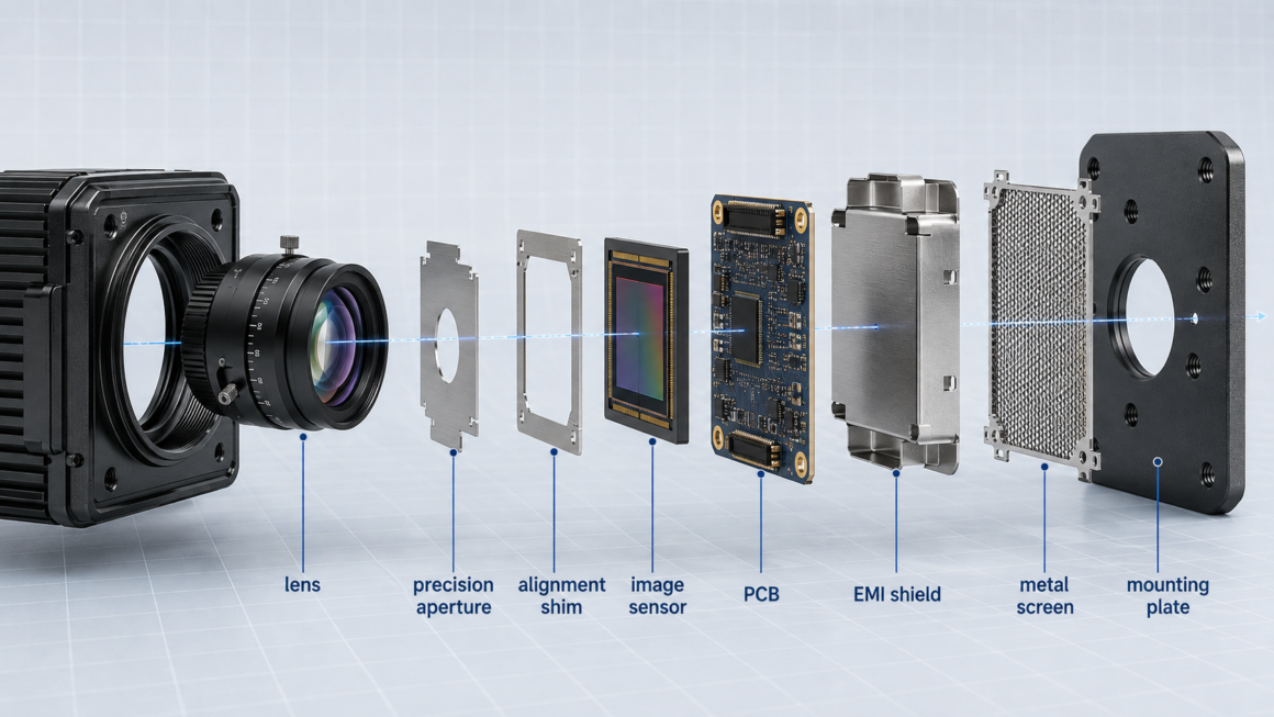
Machine vision systems are often discussed in terms of cameras, AI algorithms, and image-processing software. But software can only analyze the image that the physical system is able to capture. Camera alignment, sensor openings, shielding, airflow, and mechanical spacing can all affect the quality and stability of the data entering the system. For thin metal components with detailed features, chemical etching provides one manufacturing option for supporting this physical layer.
How Machine Vision Systems Work
A machine vision system usually follows a simple chain:
Lighting → Object → Lens and Camera → Image Sensor → Image Processing → Inspection Decision
Lighting makes important features visible. The lens directs light toward the sensor. The camera converts that optical information into a digital image.
Software then analyzes the image to detect defects, measure dimensions, read codes, identify objects, or guide a robot.
This creates a strong link between physical hardware and software performance. If the captured image is inconsistent, poorly aligned, or affected by interference, the algorithm receives poorer input.
Why Hardware Precision Matters
Machine vision systems are sensitive to the position of components.
A small change in camera height can change the field of view. Sensor alignment can affect where an object appears in the image. Optical openings can influence how much light reaches a detector.
Mechanical vibration can also shift components during operation.
This means hardware design must consider:
- Camera positioning.
- Sensor alignment.
- Aperture geometry.
- Mechanical spacing.
- Airflow.
- Electrical interference.
- Mounting repeatability.
The software layer cannot always correct information that was never captured correctly in the first place.
Sensor Apertures and Precision Plates
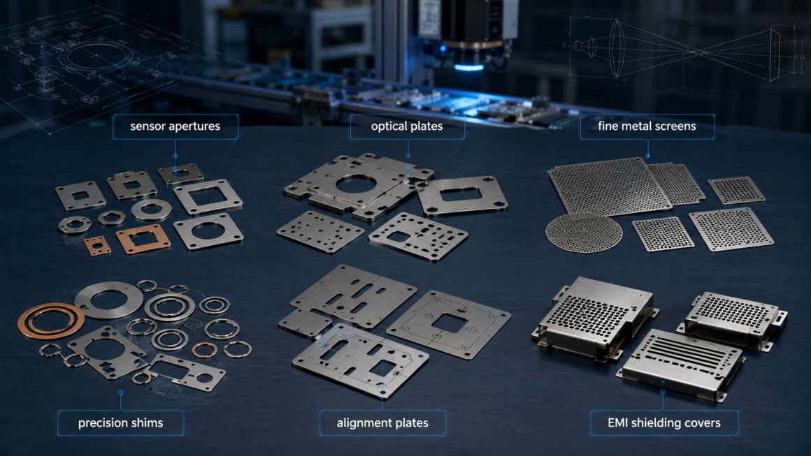
Machine vision hardware may use metal apertures, masks, sensor plates, or alignment components around optical and sensing areas.
An aperture controls the physical opening through which light or another signal passes. Its geometry can influence the area exposed to the sensor.
These components may include small holes, slots, narrow openings, alignment features, and complex outer profiles.
When several features must be positioned accurately on a thin metal part, manufacturing becomes an important part of the design process.
Fine Metal Screens for Protection and Airflow
Vision systems often operate in industrial environments where dust, debris, heat, and moving equipment are present.
Cameras and electronic modules may require ventilation while still needing physical protection around openings.
Fine metal screens can provide a controlled open area for airflow while helping protect internal hardware from larger particles.
The screen design can include repeated holes, slots, or mesh patterns. Engineers can adjust aperture geometry, open area, outer profile, and mounting features according to the equipment.
A screen designed for cooling an electronic enclosure may look very different from one used to protect a sensor opening.
Shims and Alignment Components
Machine vision depends on repeatable positioning.
Precision shims and spacers can help control the distance between a camera, sensor, lighting module, PCB, or mechanical housing.
They may be used to adjust mounting height, maintain a defined gap, or improve repeatability between assemblies.
Although shims are often simple flat components, they can require non-standard profiles, internal openings, slots, or alignment tabs.
Their value comes from controlling physical spacing within the complete system.
Managing Interference Around Vision Electronics
Modern inspection systems can combine cameras, processors, lighting drivers, communication modules, motors, and power electronics within the same machine.
These components can create electromagnetic noise.
Thin EMI shielding covers can help protect selected electronic areas or contain emissions near their source.
A shielding blank may include ventilation grids, grounding contacts, mounting feet, identification marks, and fold lines before forming.
Shielding performance depends on the complete design. Grounding, seams, openings, materials, PCB layout, and assembly must all be considered together.
How Chemical Etching Works
Chemical etching, also called photochemical etching or photo etching, removes selected areas from a sheet of metal.
The metal is cleaned and coated with a light-sensitive photoresist. Digital artwork defines the required component geometry.
Ultraviolet exposure transfers the pattern to the coated sheet. After development, an etchant removes the unprotected material.
The remaining parts are then stripped, cleaned, and inspected.
This process can create holes, slots, grids, apertures, tabs, identification features, and complex outer profiles in one flat component.
Because no cutting tool presses directly against the sheet, chemical etching avoids direct mechanical cutting force on thin metal.
Why Etching Fits Machine Vision Hardware
Machine vision components often combine thin materials with detailed flat geometry.
A sensor plate may contain several apertures, mounting holes, alignment features, and an outer profile. A metal screen may contain hundreds of repeated openings. A shielding blank may combine ventilation, grounding, mounting, and folding features.
Chemical etching can define these features through the same digital pattern.
It also supports design changes during development.
A prototype camera module may need a larger optical opening. A screen may require more airflow. A shim may need a different profile. A shield may need another ventilation section.
Because the geometry comes from digital artwork, engineers can revise the design without creating a new hard stamping die for every change.
This makes the process useful for prototype development, engineering validation, pilot builds, and selected repeat-production programs.
From Image Capture to Software Decision
For developers and automation engineers, the complete information chain is important:
Physical Object → Optical Opening → Camera → Digital Image → Vision Algorithm → Decision
Each stage depends on the one before it.
If an optical opening is poorly positioned, the camera may capture the wrong area. If a sensor module moves under vibration, calibration may change. If electronics experience interference, communication or image stability may be affected.
This does not mean every machine vision problem is mechanical.
It means software, optics, electronics, and mechanical hardware should be designed as one system.
Where Machine Vision Is Used
Machine vision appears across many industries.
Electronics manufacturers use it to inspect assemblies and components. Automotive factories use cameras for dimensional checks and robotic guidance.
Packaging lines can check labels, seals, and product placement. Logistics systems use vision for identification and sorting.
Medical manufacturing, food production, semiconductor inspection, robotics, and precision engineering also use automated visual inspection.
The required hardware depends on image resolution, inspection speed, environment, field of view, mounting space, and system architecture.
When Other Manufacturing Methods Make More Sense
Chemical etching is not the right process for every machine vision component.
Camera housings and thick mechanical structures may be better suited to CNC machining or die casting. Large brackets can often be laser cut or machined.
Simple parts produced in very high volumes may justify stamping tools.
Chemical etching becomes more attractive when the component is thin, flat, detailed, and contains many small or repeated features.
Material, thickness, tolerance, feature size, volume, forming, finishing, and total manufacturing cost should guide the final process choice.
Better Vision Starts With Better Physical Input
Machine vision performance does not depend on software alone.
The quality of the final decision begins with lighting, optics, sensing, mounting, electronics, and the physical components surrounding them.
Chemical etching can support selected thin metal parts such as apertures, screens, shims, alignment plates, and shielding blanks. It does not replace cameras, sensors, or image-processing software, but it can help create the precision hardware that supports reliable data capture.
In automated inspection, better software starts with better physical information.
About the Author